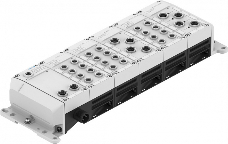
| Technical Data |
|
| Electrical control |
AP interfaceEthernet |
| Protocol |
AP |
| Dimensions (W x L x H) |
Depending on configuration |
| Grid dimension |
50.1 |
| Type of mounting |
Direct mounting via through-holeOn H-rail via accessoriesOn mounting frameScrew-clampedWith through-hole for M5 screw with accessoriesWith through-hole for M6 screw with accessoriesVia through-hole for M5 screwVia through-hole for M6 screw |
| Max. number of modules |
15 |
| Product weight |
4505200 |
| Mounting position |
Any, on H-rail: horizontal |
| Ambient temperature |
-2050 |
| Note on ambient temperature |
Observe ambient temperature derating according to IEC 61131-2:2017 |
| Storage temperature |
-2070 |
| Relative air humidity |
5 - 95%Non-condensing |
| Nominal altitude of use |
<= 2000 m ASL (> 79.5 kPa) |
| Max. installation height |
3500 |
| Note on max. installation height |
> 2000 m ASL (< 79.5 kPa)Observe ambient temperature derating according to IEC 61131-2:2017 |
| Degree of protection |
IP65IP67 |
| Note on degree of protection |
Unused connections sealed |
| Corrosion resistance class CRC |
1 - Low corrosion stress |
| Vibration resistance |
Transport application test with severity level 2 to FN 942017-4 and EN 60068-2-6 |
| Note on vibration resistance |
SG1 on H-railSG2 on direct mountingTransport application test with severity class 1 to FN 942017-4 and EN 60068-2-6 |
| Shock resistance |
Shock test with severity level 2 to FN 942017-5 and EN 60068-2-27 |
| Note on shock resistance |
30 g/11 ms to EN 60068-2-27SG1 on H-railSG2 on direct mountingShock test with severity level 1 to FN 942017-5 and EN 60068-2-27 |
| Protection class |
III |
| Protection against direct and indirect contact |
SELV/PELV power supply units required |
| Pollution degree |
2 |
| Overvoltage category |
II |
| LABS (PWIS) conformity |
VDMA24364-B2-L |
| CE mark (see declaration of conformity) |
To EU EMC DirectiveIn accordance with EU RoHS Directive |
| UKCA marking (see declaration of conformity) |
To UK instructions for EMCTo UK RoHS instructions |
| KC mark |
KC-EMV |
| Approval |
RCM trademarkc UL us listed (OL) |
| Certificate issuing authority |
UL E239998 |
| Note on materials |
RoHS-compliantFree of halogenFree of phosphoric acid ester |
| Diagnostics via LED |
(Outputs) Diagnostics per channelPower supply load (outputs)(Inputs-Outputs) Diagnostics per module(Inputs-Outputs) Status per channelDiagnostics per channelDiagnostics per moduleEtherCAT® RUNEthernet/IP communicationPROFINET communicationPower supply, el |
| Diagnostics via bus |
APDD invalidLoad switch-offCommunication faultElectronics/sensors overvoltageLoad overvoltageElectronics/sensors undervoltageLoad undervoltage |
| Diagnostics per internal communication |
Load switch-offWire breakIO-Link® eventCommunication faultShort-circuit/overload in output signalShort circuit/overload Power OUT PLShort circuit/overload Power OUT PSShort circuit/overload in sensor supplyShort circuit/overloadParameter errorsParameteris |
| Note on fieldbus interface |
All information that is relevant to CPX-AP can be read out via the Ethernet interfaces/fieldbus connections and changed depending on the function.Auto MDI, the bus module performs a crossover checkFirmware update via Ethernet interface/fieldbus interfaceI |
| Fieldbus interface |
Ethernet |
| Field bus, protocol |
ACD (Address Conflict Detection)DLR (Device Level Ring)EtherCAT®EtherCAT CoEEtherCAT Distributed Clocks (DC)EtherCAT EoEEtherCAT FoEEtherCAT Modular Device Profile (MDP)EtherNet/IPEtherNet/IP QoSEtherNet/IP QuickconnectLLDPMRP, MRPD (ring redundancy)Modbu |
| Fieldbus interface, function |
Bus connection incoming/outgoing |
| Field bus, connection type |
2x socket |
| Field bus, connection system |
M12x1, D-coded to EN 61076-2-101RJ45 to IEC 61076-3-117 (V14)SCRJ to IEC 61754-24-21 |
| Field bus, connection pattern |
28 |
| Field bus interface, electrical isolation |
yes |
| Field bus interface, transmission rate |
100 Mbit/s |
| Max. address volume, inputs |
1024 |
| Note on inputs |
EP: 488 bytesModbus: 4096 bytes |
| Max. address volume, outputs |
1024 |
| Note on outputs |
EP: 496 bytesModbus: 4096 bytes |
| Module parameters |
Configuration of voltage monitoring load supply PLBehaviour after short circuit/overload at the output |
| Channel parameters |
Activation diagnostics for IO-Link® device lostInput debounce timeMeasured value smoothingPort modeSignal rangeTarget deviceIDTarget vendorIDTarget cycle timeLower/upper limitsActivation of linear scalingUnit for temperature measurementHysteresis for moni |
| Internal cycle time |
< 1 ms |
| Configuration support |
EDS fileESI fileGSDML fileIODD file |
| Power supply, function |
Incoming electronics/sensors and load and functional earth |
| Power supply, connection type |
Plugs |
| power supply, connection system |
7/8“ to NFPA/T3.5.29M12x1, L-coded to EN 61076-2-111M18x1M8x1, A-coded to EN 61076-2-104Push-pull to IEC 61076-3-126 |
| Power supply, number of pins/wires |
45 |
| Note regarding operating voltage |
SELV/PELV fixed power supplies requiredNote voltage drop |
| Note on nominal operating voltage DC |
Protected Extra-Low-Voltage to IEC 60204-1 |
| Nominal operating voltage DC of load |
24 |
| Permissible voltage fluctuation of load |
± 25 % |
| Nominal DC operating voltage, electronics/sensors |
24 |
| Permissible voltage fluctuations for electronics/sensors |
± 25% |
| Max. power supply |
416 |
| Typ. intrinsic current consumption at nominal operating voltage for electronic system/sensors |
4010000 |
| Typ. intrinsic current consumption at nominal operating voltage, load |
310000 |
| Power failure bridging |
10 |
| Potential separation between the supply voltages electronics/sensor technology and load/valves |
Yes |
| Reverse polarity protection |
yes |